
Electrostatic discharge (ESD) is one of the most critical yet often underestimated threats in PCB design and electronic product reliability. As designs grow more compact, complex, and high-performance, featuring dense multilayer boards, BGA packages, and blind/buried via configurations—the need for robust ESD protection becomes increasingly important. Implementing effective ESD mitigation not only ensures the stability of your circuit board but also extends the overall product life cycle.
Understanding the Impact of ESD on PCB Assemblies
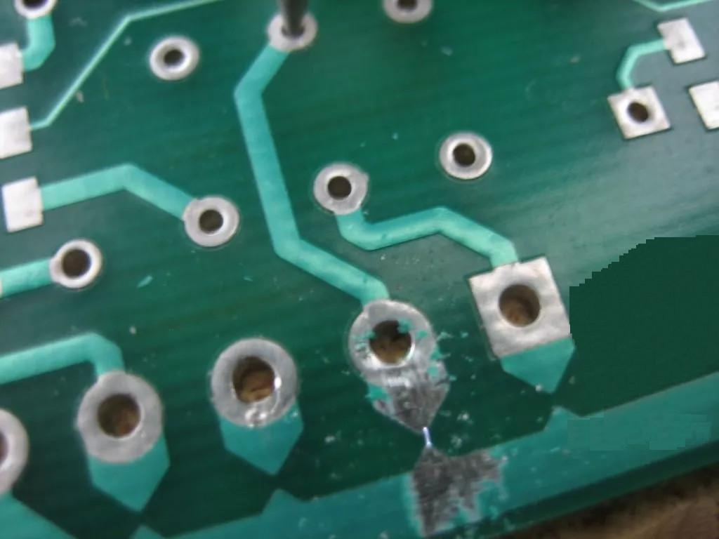
An electrostatic discharge is a sudden, brief burst of electrical energy that occurs when two objects with differing electrical potentials come into contact. This rapid release of energy can generate voltages of thousands of volts and currents that severely damage sensitive components on a PCB.
Common ESD-Induced Issues:
Circuit shorts or opens: ESD may fracture solder joints or destroy semiconductors, leading to functional failures.
Signal integrity problems: Transient spikes from ESD can introduce data errors, excessive noise, and timing issues.
Reduced product life: Even if the device doesn’t fail immediately, repeated ESD exposure can gradually weaken components, leading to early failure.
With more than 10 years in the field of PCB prototype and fabrication, PCBYES is committed to addressing these challenges by delivering ESD-resilient designs and turnkey PCBA solutions that meet quality, delivery, and cost-efficiency expectations.
Proven Techniques to Reduce ESD Damage in PCB Design
Here are several critical strategies that engineers can apply during PCB layout and design to mitigate ESD risks.
1. PCB Layout Optimization
a. Strategic placement of sensitive components
Position ESD-sensitive ICs, analog modules, and input/output connectors toward the center of the board, away from the edges where electrostatic discharge is most likely to occur.
b. Expand ground planes
A large and continuous ground plane allows electrostatic charges to quickly dissipate to ground, reducing interference with sensitive traces and components.
c. Intelligent signal routing
Maintain adequate spacing between power traces and signal lines to reduce electromagnetic interference (EMI) and minimize coupling effects. Pay special attention to high-speed signal traces—avoid routing them near board edges or high-voltage areas.
2. Implementing ESD Shielding Layers
a. Use of power and ground layers
Designing dedicated power and ground layers within a multilayer PCB enhances shielding. Incorporating protective guard traces and ground fills further reduces ESD propagation pathways.
b. Multipoint grounding techniques
Via stitching and ground vias across the board help ensure rapid charge dissipation. This avoids localized ESD accumulation, enhancing overall system robustness.
3. Protection Devices Integration
a. Transient Voltage Suppression (TVS) diodes
Place TVS diodes across key signal and power lines to absorb high-voltage transients, clamping the voltage to safe levels and protecting downstream circuitry.
b. Use of filters: capacitors and inductors
Add filter capacitors near connectors and input points to suppress high-frequency noise caused by ESD. Combined with ferrite beads or inductors, this can create effective low-pass filters that protect sensitive circuits.
4. Material Selection Matters
a. Antistatic PCB materials
Use PCB substrates and coatings with built-in antistatic properties. High-performance polymer coatings can help dissipate electrostatic charges before they reach critical components.
b. Controlled copper pours
Apply grounded copper pour regions around sensitive areas. These planes not only provide shielding but also act as ESD sinks. Ensure that copper fills are well connected to the ground plane using multiple vias for maximum effectiveness.
5. Post-Manufacturing Testing and Validation
a. ESD simulations and compliance testing
Post-assembly ESD testing simulates real-world static discharge events to validate the board’s resilience. Engineers can analyze failure modes and adjust the PCB design accordingly to improve future performance.
b. Continuous design iteration
Based on ESD test data, redesigns may include the repositioning of protection components, reinforcing ground paths, or adjusting trace spacing to achieve optimal immunity.
Real-World Application and Expertise
In practical manufacturing environments, engineers often face tight timelines and evolving design requirements. ESD damage doesn’t just affect performance; it also increases rework costs and jeopardizes customer satisfaction. That’s why integrating ESD considerations early in the design stage is critical for long-term reliability and manufacturability.
PCBYES, with its team of experienced electronics engineers and state-of-the-art manufacturing capabilities, offers PCBA turnkey services that include comprehensive ESD protection consulting, layout optimization, and rigorous testing processes. Our goal is to deliver high-quality boards and help our clients create products that last in the face of real-world challenges.
ESD may be invisible, but its effects are very real. Whether you're designing consumer electronics, industrial controllers, or IoT devices, building in ESD resilience from the start can significantly enhance product quality and durability. By focusing on intelligent layout, protective components, material choices, and thorough testing, engineers can greatly reduce the risk of ESD-related failures.
Choose reliable partners like PCBYES, who understand these technical challenges and provide more than just boards—we provide solutions.


